Under the condition of stiffness, the roughing process takes a larger cutting depth to reduce the number of passes and increase the productivity of the workpiece; the finishing generally takes a smaller depth of cut to obtain a higher surface quality. Influencing the final machining accuracy and machining efficiency of the workpiece, in addition to the reasons of the CNC machine itself, it should also be based on reasonable machining route setting, tool selection and correct installation, reasonable selection of cutting amount, programming skills and rapid control of dimensional accuracy. Aspects are considered comprehensively.
First, programming skills
CNC programming is the most basic work of CNC machining. The pros and cons of workpiece machining program directly affect the final machining accuracy and machining efficiency of the machine tool. It can be started from clever use of intrinsic programs, reduction of cumulative errors in CNC systems, and flexible use of main programs and subroutines.
1, flexible use of the main program and subroutines
In the processing of complex molds, it is generally processed in the form of multiple molds. If there are several identical shapes on the mold, the relationship between the main program and the subprogram should be used flexibly, and the subroutine should be called repeatedly in the main program until the machining is completed. Not only can the consistency of the processing dimensions be ensured, but also the processing efficiency can be improved.
2, reduce the cumulative error of the CNC system
In general, the incremental programming is used to program the workpiece. It is the previous one to process the reference. In this way, continuous execution of multi-segment programs will inevitably produce a certain cumulative error. Therefore, in the programming, try to use absolute mode to program, so that each block is workpiece. The origin is the reference, which can reduce the cumulative error of the CNC system and ensure the machining accuracy.
Machining accuracy is mainly used to produce product grades, and machining accuracy and machining tolerance are terms used to evaluate the geometric parameters of the machined surface. However, the actual parameters obtained by any processing method are not absolutely accurate. From the function of the parts, as long as the machining error is within the tolerance range required by the part drawing, it is considered that the machining accuracy is guaranteed.
Machining accuracy refers to the actual geometric parameters (size, shape and position) after machining the part. You want to learn UG programming to receive learning materials. The group 496610960 can help you to match the ideal geometric parameters. The difference between them is called the machining error. The size of the machining error reflects the level of machining accuracy. The greater the error, the lower the machining accuracy, and the smaller the error, the higher the machining accuracy. The following is a brief introduction to the methods to improve the machining accuracy of the workpiece:
First, adjust the process system
(1) Trial cutting adjustment by trial cutting - measuring size - adjusting the tool's cutting amount - cutting cutting - retrying, and so on until the desired size is reached. This method has low production efficiency and is mainly used for single-piece small batch production.
(2) The adjustment method obtains the required size by adjusting the relative positions of the machine tool, the jig, the workpiece and the tool in advance. This method has high productivity and is mainly used for mass production.
Second, reduce machine tool error
(1) The rotation accuracy of the bearing should be improved:
1 select high-precision rolling bearings;
2 using high-precision multi-oil hydraulic bearing;
3 using high precision hydrostatic bearings
(2) Improve the accuracy of the parts with the bearing:
1 Improve the processing precision of the box support hole and the spindle journal;
2 Improve the machining accuracy of the surface matched with the bearing;
3 Measure and adjust the radial runout range of the corresponding part to compensate or cancel the error.
(3) Appropriate preloading of rolling bearings:
1 can eliminate the gap;
2 increase the bearing stiffness;
3 Homogenize rolling element error.
(4) Make the spindle rotation accuracy not reflected on the workpiece
Third, reduce the transmission chain transmission error
(1) The number of transmission parts is small, the transmission chain is short, and the transmission precision is high;
(2) Adopting the speed reduction transmission is an important principle to ensure the transmission accuracy, and the transmission ratio should be smaller as the transmission pair is closer to the end;
(3) The accuracy of the end piece should be higher than other transmission parts.
Fourth, reduce tool wear
(1) Re-sharpening must be performed before the tool size wear reaches the stage of sharp wear
(2) Use special cutting oil for sufficient lubrication
(3) Tool material should meet the process requirements
Fifth, reduce the deformation of the process system
(1) Improve the rigidity of the system, especially the stiffness of the weak link in the process system;
(2) Reduce the load and its changes
Sixth, reduce the thermal deformation of the process system
(1) Reduce heat generation and isolation heat source of heat source
(2) Equilibrium temperature field
(3) Adopt reasonable machine tool component structure and assembly standard
(4) Accelerate to achieve heat transfer balance
(5) Control the ambient temperature
Seven, reduce residual stress
(1) adding a heat treatment process for eliminating internal stress;
(2) Reasonably arrange the process.
The above is the method of reducing the error of the workpiece, and the reasonable arrangement of the process can effectively improve the accuracy of the workpiece.
Second, a reasonable set of processing routes
Properly setting the processing route and processing sequence is an important basis for optimizing the machining program of the workpiece. It can be considered in terms of the machining path and the way of feeding.
In the CNC milling of workpieces, you want to learn UG programming to receive learning materials. Group 496610960 can help you to select the appropriate feeding method in combination with the process requirements of the workpiece to ensure the cutting precision and processing efficiency of the workpiece. When milling the outer contour of the plane workpiece, the cutting and cutting path of the tool should be arranged. Try to cut in and out along the extension of the contour curve to avoid knife marks at the junction. At the same time, in milling, whether down milling or up milling should be selected according to the workpiece.
Third, the choice of tools and the correct installation
Whether it is CNC machining or general machining, the tool is directly applied to the workpiece, so its selection and installation are the most important factors in the machining accuracy and surface quality of the workpiece. In particular, the workpiece is machined on a CNC machining center, and the tool is stored in the tool magazine beforehand. Once the machining is started, it cannot be replaced at will. Therefore, the general principle of tool selection is: easy installation and adjustment, good rigidity, durability and high precision.
Fourth, the reasonable choice of cutting amount
The determination of the cutting amount is an important part of the CNC machining process. Its size is an important parameter of the main motion and feed motion of the machine tool, which has an important influence on the machining accuracy, machining efficiency and tool wear of the workpiece. The choice of cutting amount includes cutting speed, back-feeding amount and feed rate. The basic selection principle is: roughing takes a larger depth of cut to reduce the number of passes and increase the productivity of the workpiece; the finishing generally takes a smaller depth of cut to obtain a higher surface quality.
Single Girder Overhead Crane with Electric Hoist is composed of girder weld by steel plate and I-steel, end girder, electric hoist and travelling mechanism. the electric hoist runs along the lower flange of the I-steel of the girder to accomplish article hoisting. It is light structure, easy installation and maintenance, and widely used for different places like factories, warehouse and material yards.
We have kinds of Single Beam Overhead Crane to choose from:
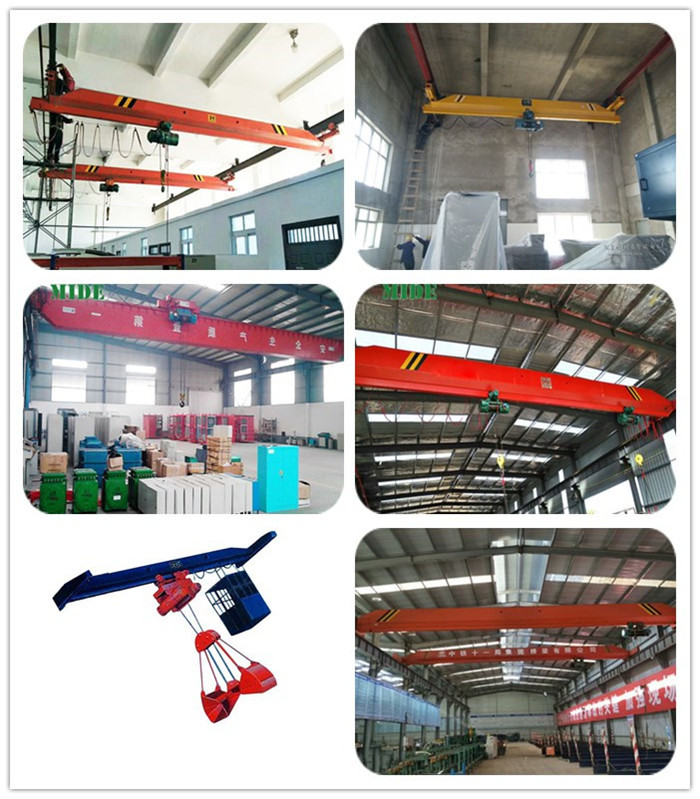
Electric single beam suspension Overhead Crane , LDP low headroom single girder crane, LDE electric single girder crane with two hoists
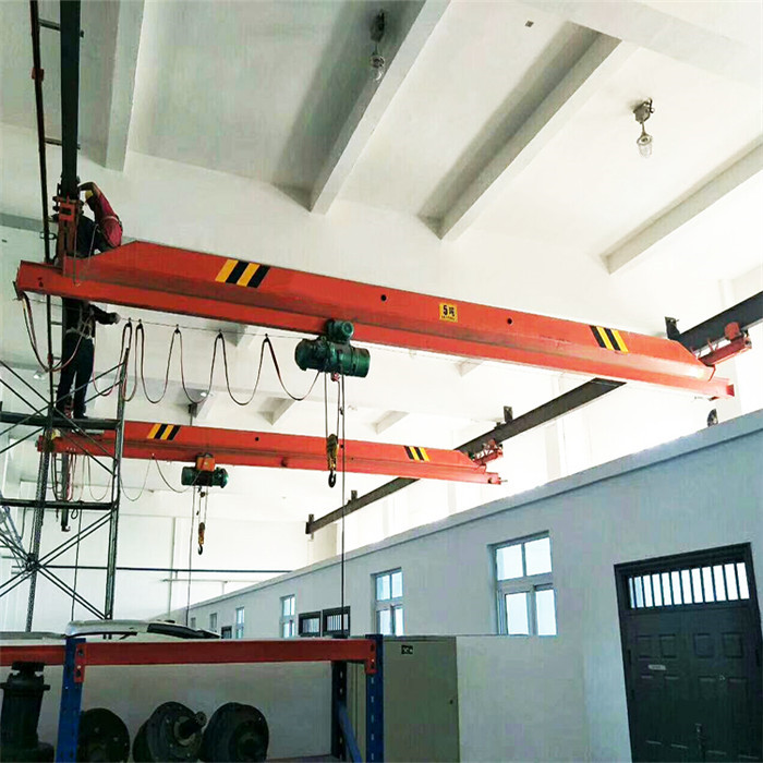
LX Electric Single Beam Suspension Overhead Crane is applicable in factories and warehouses where the height from the rail surface to the lower edge of the truss is equal to or shorter than 500mm.The trolley is equipped with a specific electric hoist that features flexible structure and reliable and safe operation. If clients have special requirements on the span, our company is able to carry out design and production of non-standard equipment.
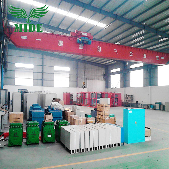
LDP model motor-driven single beam crane belongs to very low clearance light duty Lifting Equipment. Electric hoist is at on side of main girder, so can increase service space of hook and reduce the cost. With advantages of big trolley tread, smooth traveling, light structure, strong rigidity, delicate operation, low noise, safety and reliability and beautiful exterior, it is widely used in the situation that clearance height of workshop is low.
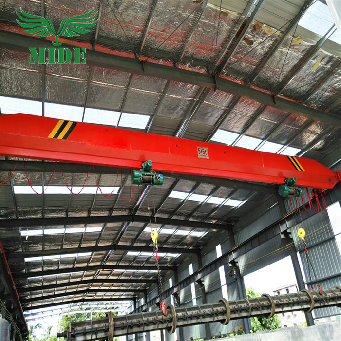
LDE electric single girder crane is developed on the base of LD single beam crane, on its single beam suspending two electric hoists. These two sets of hoist can not only be single action and also linked action, this product can lift long work pieces in workshops, warehouses and other work sites, apply to electroplating, cement pipe and steel base etc.
All you need to do is tell us the information as below:
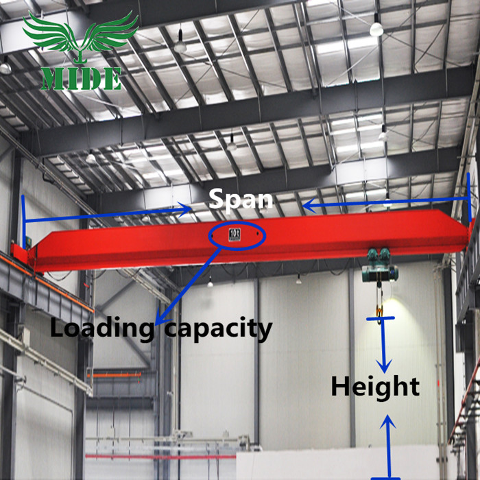
Single Girder Overhead Crane
Single Girder Overhead Crane,Single Girder Bridge Crane,Single Girder Crane Design,Single Hoist Overhead Crane,Single Beam Overhead Crane,Single Beam Bridge Crane
Jiangxi Mide Industrial Co., Ltd. , https://www.midecrane.com