Explore our complete guide of steel flanges, which will make you deeply understand what exactly steel flange is and according to that you can choose it as per your requirement of applications.
It is usually attached to other pipe fitting by using welding attachments and sealed to other flanges by using bolts and gaskets. Flange, connects various things that we use regularly in industrial process, such as for using in water pipelines to oil filtration machinery, food processing manufacturing and pressure vessels, etc.
All these industrial elements were manufactured in various specifications over years and each offer crucial role and their roles expands over several industries.
It is essential to keep the pipes connected safely in order to avoid leakages in the piping system. Flanges keeps the pipe connected accurately and help it work safely for a longer duration.
Table of contents
- Steel Flanges Specification
- Different Types of Flanges
- Steel Pipe Flange Material Grades
- Galvanized Pipe Flange Working Pressure
- Steel Flange Dimension Chart
- WNRF Flange Weight Chart
- Steel Flange Face Types
- Reducing Weld Neck Flange Thickness Chart
- Steel Pipe Flange Pipe Flange Torque Chart
- Weld Neck Pipe Flange Bolt Chart
Steel Flanges Specification
| Steel Flanges Size |
|
|---|---|
| Flange Face Types |
|
| WNRF Flange Standards |
|
| Steel Pipe Flange Pressure class |
|
| Steel Flanges Types |
|
| Steel Flanges Manufacturer in India, Buy Weld Neck and Galvanized Pipe Flange in Different Sizes at Lowest Price in India | |

Manufacturing standard of pipe flanges is ASME B16.5
It includes NPS ½ to NPS 24 metric inches, which covers of pressure-temperature ratings, dimensions, tolerance, materials, sizes, tolerances, marking, testing, and opening method of flanges.
The flange class rating includes of 150, 300, 400, 600, 900 and 1500 are available in sizes from NPS ½ to NPS 24 metric inches, and flange class rating of 2500 are available in sizes NPS ½ to NPS 12 are in metric and U.S common units with diameter of bolts and flange bolt holes stated in inch units.
ASME B16.5 flange is made from forged or cast materials. Blind flanges and specific reducing flanges are fabricated from forged, cast or plate materials. In this standard also includes requirements and suggestions with regards to flange bolting, flange gasket and even flange joints.
Different Types of Flanges
| Weld Neck Flanges | 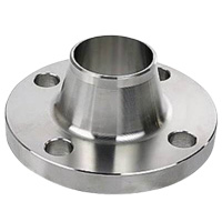 |
|
|---|---|---|
| Slip On Flanges | 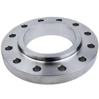 |
|
| Socket Weld Flanges | 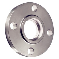 |
|
| Lap Joint Flanges | 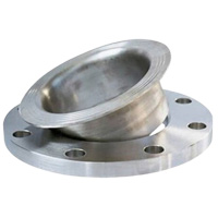 |
|
| Threaded Flange | 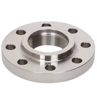 |
|
| Blind Flange | 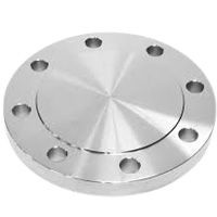 |
|
| Orifice Flange | 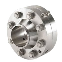 |
|
| Long Welding Neck Flange | 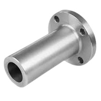 |
|
| Weldoflange and Nipoflange | 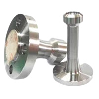 |
|
| Expander and Reducing Flange | 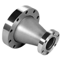 |
|
Steel Pipe Flange Material Grades
| Material | Grades | Features |
|---|---|---|
| Carbon steel |
|
|
| Stainless steel |
|
|
| Alloy steel |
|
|
| Duplex |
|
|
| Super duplex |
|
|
| Nickel Alloys Flanges |
|
|
Reducing weld neck flange have pressure rating of class 150 to class 2500
ASME creates the flange class, taking into account there are several pressure and temperature ratings. There are seven classes i.e. 150, 300, 400, 600, 900, 1500 and 2500. And the reducing weld neck flange can be worked at this pressure rating of class. The pressure rating specifies the highest tolerable pressure at a stated temperature. For instance, a class 2500 flange can resists more pressure and it is heavier compared to 1500 flange. Here, the class 2500 flange signifies that the flange is workable at this rated temperature without getting crack or damaged.
Galvanized Pipe Flange Working Pressure

| Working Pressure Bar [psi] | ||||||||||||
|---|---|---|---|---|---|---|---|---|---|---|---|---|
| Temp (°C) | (°F) | 29 – 38 | (-20.2 – 100) | 50 | -122 | 100 | -212 | 150 | -302 | 200 | -392 | 250 |
| Class | 150 | 19.6 | -284 | 19.2 | -278 | 17.7 | -257 | 15.8 | -229 | 13.8 | -200 | 12.1 |
| 300 | 51.1 | -741 | 50.1 | -723 | 46.6 | -675 | 45.1 | -654 | 43.8 | -635 | 41.9 | |
| 400 | 68.1 | -987 | 66.8 | -968 | 62.1 | -900 | 60.1 | -871 | 58.4 | -846 | 55.9 | |
| 600 | 102.1 | -1480 | 100.2 | -1452 | 93.2 | -1351 | 90.2 | -1307 | 87.6 | -1270 | 83.9 | |
| 900 | 153.2 | -2220 | 150.4 | -2180 | 139.8 | -2026 | 135.2 | -1959 | 131.4 | -1904 | 125.8 | |
| 1500 | 255.3 | -3700 | 250.6 | -3632 | 233 | -3377 | 225.4 | -3267 | 219 | -3174 | 209.7 | |
| 2500 | 425.5 | -6167 | 417.7 | -6054 | 388.3 | -5628 | 375.6 | -5443 | 365 | -5290 | 349.5 | |
| Temp (°C) | (°F) | -482 | 300 | -572 | 325 | -617 | 350 | -662 | 375 | -707 | 400 | -752 |
| Class | 150 | -175 | 10.2 | -148 | 9.3 | -135 | 8.4 | -122 | 7.4 | -107 | 6.5 | -94.2 |
| 300 | -607 | 39.8 | -577 | 38.7 | -561 | 37.6 | -545 | 36.4 | -528 | 34.7 | -503 | |
| 400 | -810 | 53.1 | -770 | 51.6 | -748 | 50.1 | -726 | 48.5 | -703 | 46.3 | -671 | |
| 600 | -1216 | 79.6 | -1154 | 77.4 | -1122 | 75.1 | -1088 | 72.7 | -1054 | 69.4 | -1006 | |
| 900 | -1823 | 119.5 | -1732 | 116.1 | -1683 | 112.7 | -1633 | 109.1 | -1581 | 104.2 | -1510 | |
| 1500 | -3039 | 199.1 | -2886 | 193.6 | -2806 | 187.8 | -2722 | 181.8 | -2635 | 173.6 | -2516 | |
| 2500 | -5065 | 331.8 | -4809 | 322.6 | -4675 | 313 | -4536 | 303.1 | -4393 | 289.3 | -4193 | |
Standard size range of socket weld and slip on flanges is 1/2″ to 24″
The range of standard size socket weld and slip on flanges are important for several industries as it gives fastening to the piping system. Socket weld and slip on flange are usually manufactured in the standard from ½†to 24â€.
The categorization and distinction between the flanges from countries to countries are important to understand for flawless combination and consistency in global projects.
Flange standardization gives safety and similarity in the broad range of global industries. It enables global trade by offering a common base for fabricators, suppliers and consumers.Â
Steel Flange Dimension Chart

| NPS | 01/2 | 03/4 | 1 | 1 1/ 2 | 2 | 3 | 4 | 5 | 6 |
|---|---|---|---|---|---|---|---|---|---|
| O.D.(Inch) | 3.5 | 3.88 | 4.25 | 5 | 6 | 7.5 | 9 | 10 | 11 |
| SORF Bore Inner Dia (MM) | 9.65 | 11.17 | 34.54 | 49.53 | 61.97 | 90.67 | 116.07 | 143.7 | 170.68 |
| Bolt Holes No | 4 | 4 | 4 | 4 | 4 | 4 | 8 | 8 | 8 |
| Holes Dia (MM) | 15.74 | 15.74 | 15.74 | 15.74 | 19.05 | 19.05 | 19.05 | 22.35 | 22.35 |
| Bolt Circle (Inch) | 2.38 | 2.75 | 3.12 | 3.88 | 4.75 | 6 | 7.5 | 8.5 | 9.5 |
| WNRF Bore Inner Dia (MM) | 22.35 | 27.68 | 26.67 | 40.89 | 52.57 | 77.97 | 102.36 | 128.2 | 154.17 |
| Dia Hub Base (Inch) | 15.74 | 20.82 | 1.94 | 2.56 | 3.06 | 4.25 | 5.31 | 6.44 | 7.56 |
| Min WT (MM) | 1.19 | 1.5 | 12.7 | 15.74 | 17.52 | 22.35 | 22.35 | 22.35 | 23.87 |
| RF Dia(Inch) | 1.38 | 1.69 | 2 | 2.88 | 3.62 | 5 | 6.19 | 7.31 | 8.5 |
| NPS | 8 | 10 | 12 | 16 | 18 | 20 | 22 | 24 | |
| O.D.(Inch) | 13.5 | 16 | 19 | 23.5 | 25 | 27.5 | 29.5 | 32 | |
| SORF Bore Inner Dia (MM) | 221.48 | 276.35 | 327.15 | 410.46 | 461.77 | 513.08 | 564.38 | 615.95 | |
| Bolt Holes No | 8 | 12 | 12 | 16 | 16 | 20 | 20 | 20 | |
| Holes Dia (MM) | 22.35 | 25.4 | 25.4 | 28.44 | 31.75 | 31.75 | 35.05 | 35.05 | |
| Bolt Circle (Inch) | 11.75 | 14.25 | 17 | 21.25 | 22.75 | 25 | 27.25 | 29.5 | |
| WNRF Bore Inner Dia (MM) | 202.69 | 254.5 | 304.8 | 387.35 | 438.15 | 488.95 | 539.75 | 590.55 | |
| Dia Hub Base (Inch) | 9.69 | 12 | 14.38 | 18 | 19.88 | 22 | 24.25 | 26.12 | |
| Min WT (MM) | 26.92 | 28.44 | 30.22 | 35.05 | 38.1 | 41.14 | 44.45 | 45.97 | |
| RF Dia(Inch) | 10.62 | 12.75 | 15 | 18.5 | 21 | 23 | 25.25 | 27.25 |
WNRF Flange Weight Chart
| NPS | 1/2 | 3/4 | 1 | 1¼ | 1½ | 2 | 3 | 4 | 5 |
|---|---|---|---|---|---|---|---|---|---|
| WNRF (KG) | 0.9 | 0.9 | 1.4 | 1.4 | 1.8 | 2.7 | 5.2 | 7.4 | 9.5 |
| SORF (LBS) | 1.1 | 1.98 | 1.98 | 3.08 | 3.08 | 5.07 | 9.03 | 13 | 14.99 |
| BRF (LBS) | 1.98 | 1.98 | 1.98 | 3.08 | 3.96 | 5.07 | 9.03 | 16.97 | 19.84 |
| NPT (KG) | 0.5 | 0.9 | 0.9 | 1.4 | 1.4 | 2.3 | 4.1 | 5.9 | 6.8 |
| LJRF (KG) | 0.5 | 0.9 | 0.9 | 1.4 | 1.4 | 2.3 | 4.1 | 5.9 | 6.8 |
| SWRF (LBS) | 1.98 | 1.98 | 1.98 | 3.08 | 3.08 | 5.07 | 9.03 | 13 | 14.99 |
| NPS | 6 | 8 | 12 | 14 | 16 | 18 | 20 | 22 | 24 |
| WNRF (KG) | 11.7 | 18.9 | 39.6 | 51.3 | 63 | 74.3 | 88.7 | 101.3 | 120.6 |
| SORF (LBS) | 18.95 | 29.76 | 63.49 | 89.28 | 105.16 | 128.97 | 163.8 | 183.64 | 218.25 |
| BRF (LBS) | 26.89 | 46.73 | 122.13 | 138.8 | 178.57 | 218.25 | 282.85 | 352.29 | 426.59 |
| NPT (KG) | 8.6 | 13.5 | 28.8 | 40.5 | 44.1 | 58.5 | 74.3 | 83.3 | 99 |
| LJRF (KG) | 8.6 | 13.5 | 28.8 | 47.3 | 63 | 72 | 87.8 | 110.3 | 123.8 |
| SWRF (LBS) | 18.95 | 29.76 | 63.49 | 89.28 | 97.22 | 128.97 | 163.8 | 183.64 | 218.25 |
Steel pipe flanges are available in different faces like RF, FF and RTJ
These are the three most important and most commonly used types of flange faces.
A raised face flange has a circular shape sealing face which extends from the flange bolting circle plane. It is available in all pressure class, therefore it is utilize for a broad range of temperature and pressure ratings. Its prime purpose is to compress more pressure on a smaller gasket part, whereby it increases the pressure capability of the joint. It is most commonly used for oil, gas and chemical engineering industries.
As its name signifies flat face flange doesn’t have any lump or raised surfaces. It utilize a “full face†gasket and have a large exposure sealing area. It is easy to align while installation and are usually more cost-effective as compared to other type of flanges. This type of flange face is the easiest method to protect against from damages and rust. It is used by applying adherent or magnetic flange guard.
Ring-Type Joint flange are usually used for more critical applications, mainly for high pressure or temperature applications. It is fabricated to offer a leak proof seal in critical conditions where standard gasket can fail. The surface of this kind of flange are machined groove.
Steel Flange Face Types

Plain Face/ Flat Face Flange
- non-metallic gaskets
- serrated sealing surface
- low pressure applications
- pressure classes 125 and 250
Raised Face Flange
- classes 150 and 300
- Height: 1/16 inch (1.6mm)
- class 300: 1/4 inch (6.4mm) raised face


Ring-Type Joint (RTJ)
- high pressure systems((>750â°C / 1,382â°F))
- typically used for class 900 and above
- Groups: R, RX and BX

| Flange Face Type | ||||||
|---|---|---|---|---|---|---|
| Characteristics | Gasket Type | Sealing Face | Sealing Area | Pressure Class | Pressure Range | Temperature Range |
| Flat Face | Soft. Non-metallic. | Inner diameter to outer diameter. | Large | 125#, 250# | Narrow. Low pressures only. | Narrow. Low temperatures only. |
| Ring-Type Joint | Hard. | Groove in flange face. | Small | All. Generally ≥ 900#. | Broad. Generally used for higher pressures. | Broad |
| Raised Face | Non-metallic, semi-metallic. | Inner diameter to raised face outer diameter. | Medium | All. | Broad | Broad |
Check thickness and torque specs of plate flanges6
The thickness of the plate flange has a prime effect on the hardness and toughness of the connection. Which means as that, if the thickness of the flange is higher its toughness will greater and vice-a-versa.
The torque of plate flange, is the force which it can bear, a rotational force or the ratio of strength demanded to rotate an item. It is considered as the turning force utilize to move items which includes of bolts.
The torque of plate flange is essential to know the prolong life of flange. It gives a non-failing connection, such as for leak free liquid transmission, accurate gasket installation, and bolts must be screwed on the flange with accurate tension and balance over the complete face of the flange. It helps to secure two elements so that it can prevent pulling or slipping apart.
Reducing Weld Neck Flange Thickness Chart
| SCH 20 Flange | |||||||||||||||||||
|---|---|---|---|---|---|---|---|---|---|---|---|---|---|---|---|---|---|---|---|
| NPS | ½ | 1 | ¾ | 1 ¼ | 1 ½ | 2 | 3 | 4 | 5 | 6 | 8 | 10 | 12 | 14 | 16 | 18 | 20 | 22 | 24 |
| SCH 20 | – | – | – | – | – | – | – | – | – | – | 0.25 | 0.25 | 0.25 | 0.31 | 0.35 | 0.36 | 0.4 | – | 0.45 |
| Sch 80 Flange | |||||||||||||||||||
|---|---|---|---|---|---|---|---|---|---|---|---|---|---|---|---|---|---|---|---|
| NPS | ¾ | ½ | 1 ½ | 1 | 1 ¼ | 2 | 4 | 3 | 6 | 5 | 8 | 12 | 10 | 14 | 18 | 16 | 20 | 24 | 22 |
| SCH 80 | 0.15 | 0.14 | 0.2 | 0.17 | 0.19 | 0.21 | 0.33 | 0.3 | 0.43 | 0.37 | 0.5 | 0.68 | 0.59 | 0.75 | 0.93 | 0.84 | 1.03 | 1.21 | – |
| SCH 120 | |||||||||||||||||||
|---|---|---|---|---|---|---|---|---|---|---|---|---|---|---|---|---|---|---|---|
| NPS | ¾ | ½ | 1 | 1 ½ | 1 ¼ | 2 | 4 | 3 | 5 | 8 | 6 | 10 | 14 | 12 | 16 | 20 | 18 | 22 | 24 |
| SCH 120 | – | – | – | – | – | – | 0.43 | – | 0.5 | 0.71 | 0.56 | 0.84 | 1.09 | 1 | 1.21 | 1.5 | 1.37 | – | 1.81 |
Steel Pipe Flange Pipe Flange Torque Chart
| Size (MM) | 15 | 20 | 35 | 40 | 50 | 80 | 100 | 150 | 200 | 250 | 300 | 350 | 400 | 450 | 500 | 600 |
|---|---|---|---|---|---|---|---|---|---|---|---|---|---|---|---|---|
| Size (Inch) | 01/2 | 03/4 | 1 | 1 ½ | 2 | 3 | 4 | 6 | 8 | 10 | 12 | 14 | 16 | 18 | 20 | 24 |
| No of Bolt | 4 | 4 | 4 | 4 | 4 | 4 | 8 | 8 | 8 | 12 | 12 | 12 | 16 | 16 | 20 | 20 |
| Bolt Dia | ½†| ½†| ½†| ½†| 5/8†| 5/8†| 5/8†| ¾†| ¾†| 7/8†| 7/8†| 1†| 1†| 1 1/8†| 1 1/8†| 1 ¼†|
| Thread Type | UNC | UNC | UNC | UNC | UNC | UNC | UNC | UNC | UNC | UNC | UNC | UN8 | UN8 | UN8 | UN8 | UN8 |
| Bolt Stress(lb/in2) | 25,000 | 30,000 | 33,000 | 50,000 | 50,000 | 50,000 | 40,000 | 45,000 | 45,000 | 40,000 | 40,000 | 41,000 | 40,000 | 40,000 | 40,000 | 40,000 |
| Torque(lbf.ft.) | 22 | 26 | 29 | 44 | 86 | 86 | 69 | 137 | 137 | 194 | 194 | 296 | 289 | 421 | 421 | 588 |
| Torque(Nm) | 30 | 36 | 39 | 60 | 117 | 117 | 93 | 185 | 185 | 263 | 263 | 401 | 392 | 571 | 571 | 797 |
Weld Neck Pipe Flange Bolt Chart

| NPS | 01/4 | 01/2 | 03/4 | 1 | 01 1/4 | 01 1/2 | 2 | 02 1/2 | 3 | 03 1/2 | 4 | |
|---|---|---|---|---|---|---|---|---|---|---|---|---|
| Pressure Class 300 | Flange Dia | 15.74 | 15.74 | 19.05 | 19.05 | 19.05 | 22.35 | 19.05 | 22.35 | 22.35 | 22.35 | 22.35 |
| Bolt Holes Dia (MM) | 02 1/4 | 02 5/8 | 03 1/4 | 03 1/2 | 03 7/8 | 04 1/2 | 5 | 05 7/8 | 06 5/8 | 07 1/4 | 07 7/8 | |
| Bolt Circle | 3 3/8 | 3 3/4 | 4 5/8 | 4 7/8 | 5 1/4 | 6 1/8 | 6 1/2 | 7 1/2 | 8 1/4 | 9 | 10 | |
| Bolts Number | 4 | 4 | 4 | 4 | 4 | 4 | 8 | 8 | 8 | 8 | 8 | |
| Bolts Dia(MM) | 12.7 | 12.7 | 15.87 | 15.87 | 15.87 | 19.05 | 15.87 | 19.05 | 19.05 | 19.05 | 19.05 | |
| NPS | 5 | 6 | 8 | 10 | 12 | 14 | 16 | 18 | 20 | 24 | ||
| Pressure Class 300 | Flange Dia | 22.35 | 22.35 | 25.4 | 28.44 | 31.75 | 31.75 | 35.05 | 35.05 | 35.05 | 41.14 | |
| Bolt Holes Dia (MM) | 09 1/4 | 10 5/8 | 13 | 15 1/4 | 17 3/4 | 20 1/4 | 22 1/2 | 24 3/4 | 27 | 32 | ||
| Bolt Circle | 11 | 12 1/2 | 15 | 17 1/2 | 20 1/2 | 23 | 25 1/2 | 28 | 30 1/2 | 36 | ||
| Bolts Number | 8 | 12 | 12 | 16 | 16 | 20 | 20 | 24 | 24 | 24 | ||
| Bolts Dia(MM) | 19.05 | 19.05 | 22.22 | 25.4 | 25.4 | 25.5 | 25.4 | 25.4 | 25.4 | 25.4 | ||
The FZ Filter high flow filter cartridges series is a kind of external pressure type (outside-in), the filter medium is made of polypropylene melt-blown materials with loose fibrous tissue, high void fraction increased the capacity of impurity section, has deep intercept filtering effect, the larger particles impurities trapped in the fiber surface, and tiny particles are trapped in the deep place of the filter material, so that the filter efficiency has the gradients filtering effect. Available material of polypropylene, glass fiber and polyester media with Non-woven fabric drain layer. We produce standard OD size at 6"/152mm high flow cartridges, 6.30"/160mm high flow cartridges & 6.5"/165mm high flow cartridges with 20", 40" and 60" length.
High Flow Filter Cartridges,152mm Diameter High Flow Filter Cartridges,160mm Diameter High Flow Filter Cartridges,165mm Diameter High Flow Filter Cartridges
Shanghai Feizuo Environment Technology Co,.Ltd , https://www.fzfilter.com