**1. Introduction**
In metal cutting processes, the shape of chips is constantly changing. To simulate chip formation accurately, it is essential to parameterize the chip shape and calculate these parameters based on the specific machining conditions. Over the years, both domestic and international researchers have conducted extensive studies on chip shape and its formation mechanisms, leading to the development of more than a dozen chip formation models. Significant progress has been made in understanding chip flow, the mechanism of chip curling, and how chips break during the process. However, due to the complexity of chip formation, many studies remain qualitative, especially when it comes to lateral chip curling.
This paper analyzes the primary and secondary factors that influence chip shape based on its formation mechanism and deformation laws. A mathematical model is established to quantitatively calculate chip shape parameters, providing essential data for chip modeling.

**2. Chip Formation and Shape Parameters**
When a tool cuts into the workpiece, the material undergoes plastic deformation along the shear plane, forming chips. These chips are then curled and deformed by the tool’s flute, resulting in spiral-shaped chips with consistent pitch. The spiral shape is defined by parameters such as diameter (2r), pitch (p), and the angle (q) between the helical surface and the axis (as shown in Figure 1). After exiting, chips may be further deformed or broken by obstacles like the workpiece, tool, or machine, leading to various chip types. Therefore, other chip forms can be viewed as variations or combinations of spiral chips.
The key parameters affecting spiral chips include 1/rx (chip curvature in the radial direction), 1/rz (horizontal curl), and h (chip thickness). The shape parameters of spiral chips can be expressed mathematically as follows:
$$ \text{Equation (1)} $$
$$ \text{Equation (2)} $$
$$ \text{Equation (3)} $$
Numerous factors influence 1/rx, 1/rz, and q, such as the material being cut, cutting depth, tool geometry, coolant usage, and machining method. By analyzing the main influencing factors and conducting comprehensive experiments, it is possible to achieve quantitative calculation of chip shape parameters.

**3. Parameters of the Chip Axis Section**
To determine the shape of the spiral chip cross-section, parameters such as chip thickness (hch), chip width (bch), and chip offset (kch) are used (see Figure 2). Based on the cutting principle, the formulas for calculating the axial section of the chip are:
$$ h_{ch} = A_h f \sin(k_r) \quad \text{(4)} $$
$$ b_{ch} = a_p \sin(k_r) \quad \text{(5)} $$
$$ k_{ch} = \arctan(A_h \tan(k_r)) \quad \text{(6)} $$
Where $ A_h = \frac{\cos(f - \alpha)}{\sin f} $, with known parameters such as feed (f), depth of cut (ap), tool clearance angle (kr), and rake angle (α). The shear angle (f) can be obtained through experimental formulas.
**4. Calculation of Chip Curl Rate**
The chip radius (Râ‚€) is primarily influenced by the chip flute and built-up edge. Since modern carbide tools operate at high speeds, built-up edges are rarely formed, so their effect is typically ignored. When a chip flute is present, the chip flow is affected by the flute wall, causing the chip to lift and bend, resulting in an upward curl (see Figure 3). The formula for Râ‚€ is:
$$ R_0 = (w - l_f) \cos(s/2) $$
Where $ l_f = k_m h_D \sin(f + \beta - \gamma_0) \sin f \cos \beta $, $ h_D = f \cdot \sin(k_r) $. Here, w is the chip flute width, s is the groove bottom angle, km is an experimental coefficient (~2), and β is the friction angle, which can be determined from cutting forces. Let Cx be the integration coefficient for other influencing factors. Then, the chip curl rate is given by:
$$ 1 = C_x = C_x \cdot r_x \cdot R_0 \cdot (w - l_f) \cdot \cos(s/2) \quad \text{(7)} $$
**5. Calculating the Chip Curl Rate**
Currently, research on lateral chip curling is mostly qualitative. Two main factors influence lateral curl: chip lateral flow and the participation of secondary cutting edges in the width direction. Based on this, a theoretical formula for lateral curvature is derived, with unknowns adjusted using experimental coefficients.
Let D represent the chip's width deformation, and Dv = vâ‚‚ - vâ‚ be the speed difference in the length direction caused by the workpiece. The angular velocity is $ \omega = \frac{v_2}{r_{z1}} = \frac{v_1}{r_{z1} - bD} $ (see Figure 4). Using $ Dv = \frac{D}{k_{w1} bD} v_1 $ and $ D = b_{ch} - bD $, where $ k_{w1} $ is experimentally determined, the curvature caused by lateral flow is:
$$ 1 = \frac{D}{r_{z1} bD (D + k_{w1} bD)} $$
Under the same cutting thickness, when the load from the secondary cutting edge is equivalent, the transverse curvature is maximized. The greater the cutting thickness, the more significant the impact of the secondary cutting edge on the transverse curl. Let x, kw2, and aw be experimentally determined parameters for the lengths of the primary and secondary cutting edges. Then, the curvature caused by the secondary cutting edge is:
$$ 1 = \frac{k_{w2} x h_D a_w}{r_{z2}} $$
Using an optimal design approach, let $ k_{w1}, k_{w2}, $ and $ a_w $ vary within ranges [1-5], [0-1], and [0-1], respectively. Substituting into each formula yields calculated values Crz, which are compared with measured values Lrz from cutting experiments. The minimum value of $ S(Lrz - Crz)^2 $ gives the optimal set of coefficients $ k_{w1}, k_{w2}, $ and $ a_w $. Let Cz be the comprehensive coefficient for other influencing factors. The formula for the lateral curling rate is:
$$ \text{Equation (8)} $$
**6. Chip Shaving Angle Calculation**
When cutting perpendicularly, the chip flows out perpendicular to the cutting edge. In three-dimensional cutting, the chip outflow direction forms an angle with the vertical direction of the main cutting edge. This angle is approximately equal to the chip angle h. Several methods exist to analyze the flute angle. Stabler’s law suggests $ h = c l_s $. Colwell believes the chip flow direction is nearly perpendicular to the chord of the cutting edge. Wang and Mathew found that the tool tip arc radius and the inclination of the cutting edge are major factors affecting chip flow.
A quantitative method for calculating the flow angle is the flow angle regression equation:
$$ l = 0.21a_p - 0.74f^{0.424}(r_s + 0.45)^{0.68}(k_r - 16)^{1.28} \cdot 0.99g_n + c l_s $$
Where $ c \approx 0.62 - 0.67 $ is related to the workpiece material. If no tool change is required during the process, the tool parameters remain constant. Define:
$$ Cl1 = 0.21(r_s + 0.45)^{0.68}(k_r - 16)^{1.28} \cdot 0.99g_n $$
$$ Cl2 = c l_s $$
Then, the flow angle calculation simplifies to:
$$ \text{Equation (9)} $$
**7. Conclusion**
The general shape of chips is equal-pitch spiral chips. The axial section parameters hch, bch, and kch are calculated using equations (4), (5), and (6), while the shape parameters 2r, p, and q are determined via equations (1), (2), and (3). The influencing factors 1/lx, lz, and h are approximated using equations (7), (8), and (9) to obtain their parameter values. Based on the quantitative values of hch, bch, kch, 2r, p, and q, chip modeling becomes feasible.
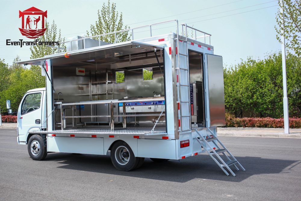
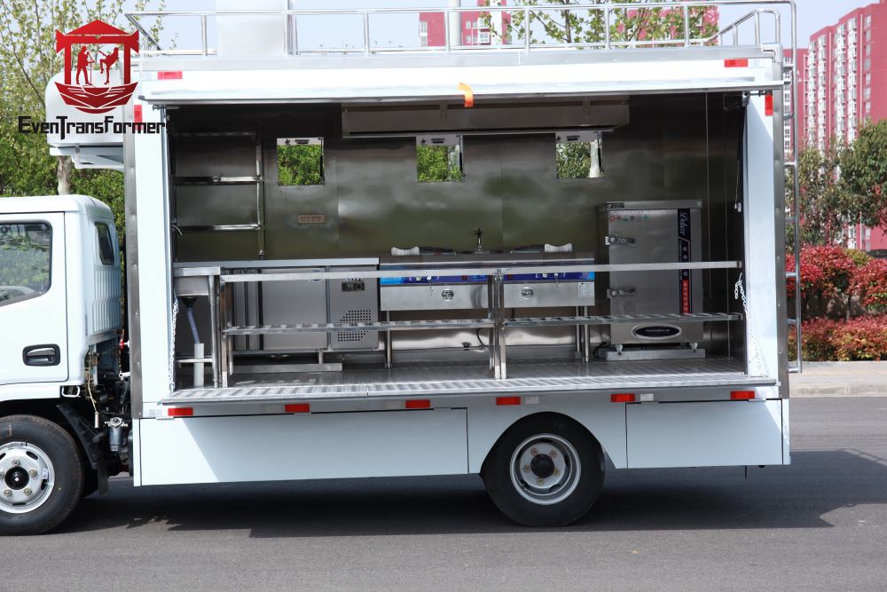
Mobile Commercial Kitchen
EVENT TECH TRANSFORMERS CO.,LIMITED well-built portable kitchens can provide you with the solutions you need anywhere. You can choose from a variety of sizes, such as our 44' and 57' trailers. Our fully equipped kitchen allows you to prepare and serve thousands of meals in hours.
Our trailers provide the perfect way to deliver event catering and food truck services on a larger scale. Seasoned culinary professionals have used our trailers and found them to be versatile and easy to maneuver. Wow your staff, guests and audience with excellence in hygiene, food preparation and service.
Mobile commercial kitchens can be built using a trailer or truck. With extra flexibility and easy shipping options, you can also prepare food to order for exceptional customer satisfaction.
If you want to be part of the action anytime, anywhere, you should add a mobile kitchen to your business. Mobile commercial kitchen trailers are the perfect solution for your next event, expanding business, or wherever you need access to an off-site kitchen. You can take our fully custom industrial mobile kitchen trailers anywhere. EVENT TECH TRANSFORMERS CO.,LIMITED has experience in event catering mobile kitchen trailers, sample kitchens, etc.


Mobile Commercial Kitchen,Mobile Retractable Kitchen,Mobile Multi-Functional Kitchen,Mobile Retractable Multi-Functional Kitchen
EVENT TECH TRANSFORMERS CO.,LIMITED , https://www.crusadetruck.com

