Anemometer probe selection: The flow rate measurement range from 0 to 100 m/s can be divided into three sections: Low speed: 0 to 5 m/s; Medium speed: 5 to 40 m/s; High speed: 40 to 100 m/s. The anemometer's thermal probe is used for accurate measurements from 0 to 5 m/s; the anemometer's rotary probe is ideal for measuring flow rates from 5 to 40 m/s; while using a pitot tube gives the best results in the high speed range. result. The correct choice of anemometer flow probes is an additional standard for temperature. Usually the anemometer's thermal sensors are used at temperatures up to ±70°C. The special probe for anemometer can reach 350°C. Pitot tube is used above 350°C.
Anemometer thermal probes: The anemometer thermal probe works on the principle that a cold-impinging air stream carries heat away from the thermal element. With a regulating switch, keeping the temperature constant, the current and the flow rate are regulated in direct proportion to each other. When thermal probes are used in turbulent flow, airflow from all directions simultaneously impacts the thermal elements, which affects the accuracy of the measurement results. When measuring in turbulent flow, the thermal anemometer flow sensor often shows higher values ​​than the swivel probe. The above phenomena can be observed during the pipeline measurement. According to the different designs of turbulence in the pipeline, it will appear even at low speeds. Therefore, the anemometer measurement process should be performed on the straight part of the pipeline. The starting point of the straight section should be at least 10 × D before the measuring point (D = pipe diameter in CM) and the ending point should be at least 4 × D after the measuring point. The fluid cross section must not have any blockage. (corners, resuspensions, etc.).
Anemometer Rotary Probe: The working principle of the anemometer rotary probe is based on the conversion of the rotation into an electrical signal, which starts with a proximity sensor and “counts†the rotation of the runner and generates a series of pulses. After the detector conversion processing, you can get the speed value. The anemometer's large-diameter probe (60mm, 100mm) is suitable for measuring turbulence in medium and small flow rates (eg at the outlet of pipes). An anemometer's small-bore probe is better suited for measuring air flow with a cross-section greater than 100 times the cross-section of the probe.
The anemometer's measurement of the vent in the exhaust gas provides a relatively uniform distribution of the airflow in the duct: a high-velocity zone is created on the surface of the free vent, and the remaining parts are in the low-velocity zone, and vortices are generated on the grid. According to the different design of the grid, the airflow cross section is relatively stable at a certain distance (about 20cm) in front of the grid. In this case, large-caliber runner anemometers are usually used for measurements. Because larger calibers can average uneven flow rates and calculate their averages over a wide range.
The anemometer was measured with a volumetric flow funnel at the suction hole: even if there was no interference with the grid at the suction, the direction of the air flow did not have a direction and the cross-sectional area of ​​the airflow was not uniform. The reason for this is the partial vacuum inside the pipe. The air is extracted from the air chamber in a funnel-like manner, even in a region that is very close to the pumping air, and there is not a place that satisfies the measurement conditions for measurement operation. If a grid measurement method with an average calculation function is used for measurement and the volumetric flow method is used to determine the measurement, only the pipe or funnel measurement method can provide repeatable measurement results. In this case, different size measuring funnels can meet the requirements for use. Using the measuring funnel, a fixed section meeting the measurement condition of the flow velocity can be generated at a certain distance in front of the sheet valve, and the center of the section is located and the section is fixed therein. The measured value obtained by the flow velocity probe is multiplied by the funnel coefficient to calculate the volumetric flow volume.
For related instruments, please see: http://?id=61
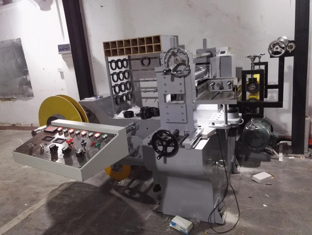
Jingye precision mechanical slitting machine is specially used for slitting various thin strips, such as copper,
 Aluminum, iron, stainless steel, up to + -0.002mm
(1). Raw material specifications 1. Material: metal strips such as copper and stainless steel strips. 2. Material width: within 420mm. 3. Material thickness: copper strip 0.05mm∽1.5mm, stainless steel 0.05mm∽1.0mm. 4. The inner diameter of the raw material roll: ï¿ 300mm. 5. Outer diameter of raw material roll:â‰¦ï¿ 1500mm.
6. Weight of raw material roll: ≤3000kg.

Stainless Steel Slitting Machine
Stainless Steel Slitting Machine,Aluminum Slitting Machine,Metal Slitting Machines Precision,Precision Metal Slitting Machiney
Dongguan Liaobu Jingye Precision Machinery Factory , https://www.dgjyjmjx.com