1. Project Overview Yunnan Jinghong Zinc & Liquor Co., Ltd. Qujing Nonferrous Metals Base Project is the competent company of Yunnan Metallurgical Group Corporation to convert the advantages of lead and zinc mineral resources into economic advantages as soon as possible, according to “Distributed Mining, Selected Mineral Processing, Centralized Smeltingâ€, Improve the industrial concentration, improve the development of process technology and equipment, combine the introduction of the world’s advanced process technology with the R&D and application of its own patented technology, combine scientific and technological innovation and management innovation, and form a new environment-friendly and energy-saving production process. The implementation of the "10th Five-Year Plan" key technological transformation projects, the project total investment of about 2 billion yuan.
The project consists of three subprojects, 60,000 tons per year of crude lead, the introduction of high-tech environmental protection and energy saving technology transformation projects, 100,000 tons/year of electrowinning technology transformation projects, and the development and utilization of environmental protection energy-saving technologies for the deep resources. The project was put into production in December 2005. At present, it has formed an annual production capacity of 100,000 tons of lead, 100,000 tons of zinc, and 260,000 tons of sulfuric acid. At the same time, it recovers valuable metals such as cadmium, copper and tellurium, and uses waste heat for power generation.
China Nonferrous Engineering Design Institute undertook the overall design of the Qujing Nonferrous Base Project and the engineering design of the lead and zinc smelting projects. The lead smelting system adopts the international advanced oxygen-enriched top-blown smelting technology. The zinc smelting system adopts the international leading 109m2 large-scale Boiling roaster and 3.2m2 large-scale plate zinc electrolysis and automatic stripping zinc production line. At the same time, it took on the integration of the automatic control system technology and equipment and software programming and debugging of the core process components in the lead and zinc smelting projects. The DCS control system of the whole plant adopts an advanced fieldbus control system in its core process. The control system was also put into production in December 2005 and passed acceptance.
2. Fieldbus Control System 2.1 Instrument Control System Development Process Instrumentation Control System In the early 70s of the 50's, due to the rapid development of electronic technology, industrial automation was dominated by the electric unit instrument cluster control system. In the 1970s, with the advent of large-scale integrated circuits, DCS (Distributed Control System), a new process control system based on micro-processing, has begun to be applied. For more than 20 years, DCS system hardware, system software and application software have been increasingly perfected, occupying an extremely important position in various production process control areas.
The fieldbus technology developed and applied now is a digital communication network technology. Digital signals with different address codes are transmitted through the same cable to realize information exchange between on-site smart meters and main control systems. The field bus system consists of three parts: field smart meter, field communication bus and computer interface. On-site smart meters include smart transmitters and valve actuators, which can have functions such as conversion, PID adjustment, calculation, and self-diagnosis.
2.2 Advantages of fieldbus control systems The fieldbus control system (FCS) composed of fieldbus has the following advantages:
(1) The FCS signal transmission is fully digitalized, from the underlying field smart meter to the communication network structure;
(2) FCS is fully decentralized, and all DCS control station I/O units and function blocks can be distributed to all field smart meters;
(3) FCS field smart meters are designed according to openness. FCS implements a fully open network standard that can completely realize resource sharing in databases in the network.
Foundation Fieldbus (FF) and Profibus Fieldbus are two types of fieldbuses that are currently used in many process control applications.
The FF fieldbus is a two-way digital communication protocol for communication between field instruments and control systems. It is designed for process control and is a fully open control system. Compared with the traditional control scheme, the installation fieldbus can be reduced. Hardware components simplify wiring structures, reduce I/O devices and reduce centralized control requirements. With fieldbus equipment management, field equipment can be maintained without the need to send technicians to loud, remote and dangerous locations. The digital valve controller enables precise and stable valve travel. Its diagnosis and maintenance function can prevent or reduce sudden stop accidents caused by valves, greatly prolong the safety production cycle of plant installations, and increase the availability of plant installations.
Profibus is also a widely used and open field bus standard. Profibus-DP can be used for high speed time applications. ProfibusDP is especially designed for communication between automation systems and decentralized peripherals.
3. Composition of Qujing Smelter Fieldbus Control System Qujing Nonferrous Base Smelter Control System consists of lead smelting DCS, PLC control system, zinc smelting DCS, PLC control system, public and auxiliary facilities DCS, PLC control system, etc. There are a total of 11 sets of DCS and more than 30 sets of PLC and inverter control systems. The DCS network structure diagram of the lead smelting part is shown in Figure 1 below.
In the lead smelting section, there are five sets of DCS control systems for ISA and waste heat boiler control systems, blast furnaces, and fuming furnace control systems, and pulverized coal preparation control systems. The ISA furnaces and waste heat boiler control systems in the lead smelting section use field buses. The control system FCS consists of engineer station, operation station, controller and I/O interface, network part and printer.
ISA furnace waste heat boiler FCS is the lead system control center. Its monitoring scope includes connection with ISA furnace smelting control system, ISA furnace waste heat boiler, ISA furnace dust collection system, lead blower room, lead circulating water, diesel The processes of the water purification station and the high water tank, the oxygen system control system, and the lead blower room control system respectively consider the communication connection with the control system.
3.1 Fieldbus control system design and selection FCS adopts Emerson company DeltaV system, fieldbus adopts FOUNDATION fieldbus, bus interface card is H1 card, including 15 bus segments Segment, at the same time, with the PLC with the fan Easy to communicate with Profibus DP communication card.
Taking into account the reliability, the FCS system controller is redundant, the communication network is redundant, and the power module is redundant.
The operating system of the engineering station and operating station is Windows XP, and the control system software is provided by Emerson. The engineering station software includes configuration, engineering, operation, and communication software packages that allow configuration switching between online inspection, engineering, and process operations. Operator station software includes operating and communication software groups. Deltav system has built-in equipment management software AMS to support the configuration of FOUNDATION fieldbus FF equipment, modify range and remote diagnosis, and with OPC and PID loop self-tuning software.
3.2 Fieldbus Instrument Selection In this design, the pressure differential pressure transmitter of the FF field instrument uses Emerson's 3051S series pressure differential pressure transmitter, and the temperature transmitter adopts the 3244 series and 848T8 temperature transmitters. The control valve adopts the Fisher DVC500 series digital valve controller. The flow meter adopts Probar flowmeter, Micromotion mass flowmeter and 87 series electromagnetic flowmeter according to different measured media.
The FF field instrument is connected to the DeltaV system through the H1 card, which is a 31.25 Kb/s low-speed control network. . One H1 card can connect up to 32 FF bus meters. H1 is divided into two network segments to connect with FF meters. In this way, each network segment can connect with 16 meters. With #18AWG (0.8mm2) shielded twisted pair, the maximum length of each segment can reach 1900m.
FF meter and branch links are:
(1) Bus with branch structure;
(2) Tree structure;
The typical HI branch connection is shown in Figure 2 - ISA furnace waste heat boiler area map.
In this design, the fieldbus junction box was designed using MTL's junction box, and part of P+F's bus junction box was added on the site.
4. Fieldbus control system design and commissioning summary 4.1 Difference between fieldbus control system and conventional engineering design Through the design and production practice of the project fieldbus, the designers think that the main differences from the conventional instrument engineering design are as follows:
(1) Instrument specification sheet The instrument specification sheet should consider the added functions as follows:
l Functional block requirements l Diagnostic requirements l Functionality of the actual functional block lLAS function The link activity adjuster LAS is a device that maintains a normal operating control program for a network segment, and it periodically transmits control instructions in the device according to a specified schedule. Only one link master device can perform LAS on an H1 network segment.
Since the PID function block is placed in the field transmitter or valve in the bus design, the actual function block position of the fieldbus instrument must be considered.
(2) Replace the instrument loop diagram with the area diagram. The loop diagram shows the connection between each cable and the field device. This method is used to ensure the accuracy of point-to-point wiring. With intelligent, non-polar equipment and FF fieldbus, these circuit diagrams are no longer necessary and can be replaced with area maps. On the area diagram of an H1 card, up to 32 instruments can be connected and the cable length can be represented. A regulator loop transmitter and valve are preferably located on one branch. In addition, the traditional DCSI/O allocation list will be replaced by the fieldbus area allocation list. For the area map, see the following typical branch diagram, as shown in Figure 2.
4.2 FCS and field instrumentation on-site operation After several stages of FCS project design, commissioning and operation, we believe that FCS is the direction of future control system development and has the following advantages:
(1) The use of field bus design reduces the amount of drawings.
Using area diagrams instead of circuit diagrams, the number of instrument diagrams is greatly reduced. And reduce the terminal distribution and wiring diagram, the instrument external pipeline connection system diagram and so on.
(2) Saves cables and installation materials.
With the H1 bus, up to 32 FF meters can be connected to one H1 card, greatly reducing the number and type of cables, reducing the number of cable protection tubes and cable trays, and reducing installation costs.
(3) Reduced operating and maintenance costs.
The application of all digital and intelligent field instrumentation and equipment management software such as AMS greatly reduces the time and expense of instrument calibration, on-site inspections, instrument fault diagnosis, and the establishment of instrument calibration and management documents is more accurate and rapid.
(4) Increased factory safety.
The use of smart meters, equipment management software, and so on, so that operators can obtain timely failure prediction, alarm and troubleshooting of the instrument in a timely and accurate, safe and reliable, so that the plant's non-planned parking time is reduced, so that production efficiency is greatly improved.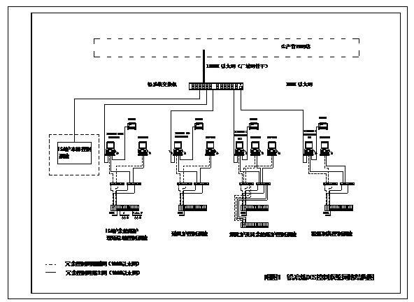
Glass Commercial Elevators,Passenger Lift,Hotel Elevator
Yineng Elevator Co., Ltd. , http://www.realever-elevator.com